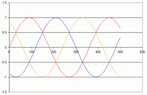
Three phase supply systems consist of three independent sinusoidal voltage waveforms with a phase angle between each phase of 120°, as shown in the graph.
These three voltages have been drawn relative to a common voltage reference (or neutral) point.
The three voltages may be supplied through a 3 wire system (most common) or with the inclusion of a neutral point via a 4 wire system.
These two systems (3 wire and 4 wire) form the basis of the vector group configuration that can be specified for a three phase transformer.

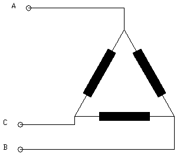
The DELTA group comes from the connection of three coils connected between the lines of a 3 wire system

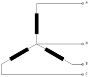
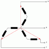
The STAR or WYE group comes from the connection of three coils from the three lines to the common neutral (or star) point.

By far the most common vector configuration of three phase transformers we manufacture is the DYN11 vector group. The first letter “D” refers to the primary configuration being a Delta connection the “Y” refers to the secondary configuration being a star connection. The letter “N” following the “Y” indicates that the neutral point which has been connected as a common point on the secondary is actually brought out as an accessible terminal. Finally there is a number that indicates the phase difference between the primary line voltages and the secondary line voltages. This number relates to the numbers on the dial of a clock and each one represents 30° of the 360° in a full circle. Numbers 1 to 5 on the clock occur when the secondary voltage leads the primary voltage while 7 to 11 the phase angle lags.
Different clock positions for phase angle shift between primary and secondary are generated by different connections between the start and finish leads of the windings of the coils. For example, in the DYN11 vector group the start leads of the secondary coils are joined together to form the neutral point. To produce the DYN5 vector group the finish leads of the secondaries would be joined to form the neutral.
Other common configurations are YY0, DD0, YD1
It should be noted that it is not possible to generate a zero phase shift between primary and secondary with a combination of delta and star windings. For this a more complex vector group the 'Zig-Zag' or inter-connected star configuration is used. In this format half of each secondary is wound on a different leg of the transformer. The secondaries are then interconnected. An example would be DZN0, here the lead angle of one leg is used to balance the lag angle of the other leg.

Delta Tap Connections
When a transformer is supplied with a delta winding for a single voltage, the interconnections between the coils are made as standard linking up to the terminals. However when the delta windings are wound with the option for taps, each individual tap is connected to its own terminal and the delta connections are made with movable link wires or bars. As standard the delta links will be supplied connected for the nominal rated voltage. When connecting the incoming leads to another tap the delta connection link wires also have to be moved to the tap.
