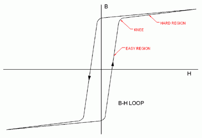
Magnetic core materials have three distinct areas relating to their behaviour as they are magnetized. These magnetic properties appear clearly on the B-H loop of the material.
B is the magnetization state of the material (Tesla)
H is the driving force related to the transformer No-load Current and the primary turns (Ampere-Turns/metre)
- Easy magnetization region
A sector whereby small changes in the net current driving the magnetization result in large changes in the magnetization state of the material.
- Hard magnetization region
A sector whereby large current changes cause only relatively small changes in the magnetization state. This region is also known as the saturation region.
- 'Knee' Transition region
This is the sector of the magnetic performance curve between the easy and hard regions. It is known as the ‘Knee’ of the curve.

Power has to be given to the core material to drive it through these magnetic changes in state and this power lost to the system is represented by the area enclosed by the B-H loop.
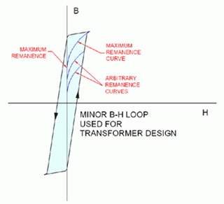
For transformer design we generally operate in the easy magnetization region up to the knee of the curve. This is known as a minor B-H loop. Operating in this region has the effect of limiting the No-Load Current and the No-Load Losses of the transformer.
When a transformer is switched off then from whatever arbitrary magnetization state it was in, it will fall back to a remanent state on the B axis of the B-H loop. Clearly the highest remanent state, and therefore worst case occurs when switched off from the maximum B field level of the minor B-H loop.

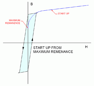
When the transformer is switched back on, the magnetization might be moved in either direction depending on the direction of the first mains cycle and by different amounts depending on the actual point of the mains cycle the voltage is applied.
The worst possible case is indicated by the curve ‘Start up’ which will drive the magnetic material far into the ‘Hard’ magnetic region, requiring a very large current to be drawn from the supply.
This is known as the In-rush current.
Although this worst case is only one possible outcome from an infinite number of possibilities, the installation system must account for the chance of this high current occurring.

Over successive mains cycles this excursion into the ‘Hard’ region will reduce as the unit settles back to a normal symmetrical B-H minor loop so successively smaller current pulses will be drawn on each cycle.
Typically the first pulse will draw a current of 10 to 15 times the nominal rated current of the transformer for a duration of approximately a quarter of the mains cycle.

Transformers can be designed to reduce the In-rush current to specified levels for specific applications if required by reducing the operational magnetization level. This will reduce the maximum remanent state of the core and reduce the maximum flux variation during start up.
Also when such large currents are flowing the primary resistance can become significant in limiting the in-rush current, therefore concentrically winding the primary coil outside of the secondary coil will increase the primary resistance to assist in reducing the in-rush currents.
