D.C. RECTIFICATION
Transformers by their nature can only operate with the application of a continuously varying input voltage, one that swings from positive to negative and back again, the A.C. supply. (alternating current)
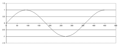
The requirement for some electrical applications of a D.C. (direct current), or positive only, supply requires a method of converting the A.C. output of the transformer into a D.C. waveform. This conversion process is known as “Rectification”. A diode is a semiconductor device that will only permit a current to flow in one direction, in simple terms it is a device with a zero resistance when a positive voltage is applied across it and an infinite resistance when a negative voltage is applied across it.
Single Phase Systems
Taking an A.C. voltage waveform from the output of a transformer to the load via a diode will result in the following D.C. waveform.
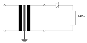
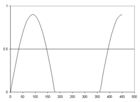
This is a very basic form of rectification known as “Half Wave Rectification”.
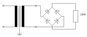
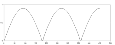
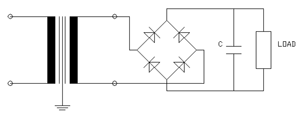
By using 4 diodes in the configuration shown below-left it is possible to achieve the D.C. waveform shown below-right. This is known as “Full Wave Rectification” and the diode configuration is referred to as a “Bridge Rectifier”. This is the most common rectifier format.
An alternative method of achieving full wave rectification involves a 2 diode system with a centre tap on the transformer as shown below
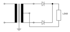
This is known as a “Bi-phase Rectifier”.
Each of these systems is providing a D.C. output for a load but it is not a steady voltage D.C. Quite often it will be adequate to supply the load e.g. the coil in a contactor or a D.C. motor but some loads will require a steady D.C. voltage, similar to that of a battery. This can be achieved by the use of “Smoothing” components; Capacitors and Inductors. The varying D.C. supply circuits shown above are therefore referred to as “Un-smoothed”.
Capacitor Smoothing
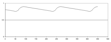
The following waveform shows the effects of placing a capacitor onto the output of the un-smoothed circuit. The effect now is to produce a reasonably stable D.C. voltage level with a small ripple voltage, the size of which is determined by the load current and the size of the capacitor.
Further levels of smoothing can be achieved by using inductors and capacitors to produce an output filter. The use of this type of filter is generally governed by the size and cost of inductors and capacitors, versus the capacitors only required to achieve the required level of smoothing.
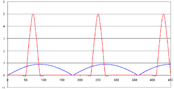
When the D.C. is smoothed using a capacitor the current waveform changes quite significantly. Given a linear load the current waveform on an unsmoothed D.C. supply will follow the voltage waveform as indicated by the blue curve below, however the introduction of the smoothing capacitor will alter the current waveform to that of the red curve. This will require the transformer to be designed to compensate for the larger voltage drop associated with its regulation to maintain a specific D.C. voltage level.
For safety reasons Carroll & Meynell D.C. supplies using capacitors in the design are fitted with “Discharge Resistors” to drain the capacitor of its charge when the unit is switched off without a load connected.
3 Phase Systems
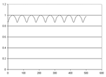
The three phase rectifier operating on the output of a transformer as shown below will automatically, as a direct result of the overlapping of the various phases, produce a smoothed D.C. output with a 4.5% ripple.
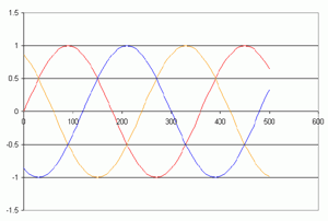
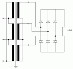
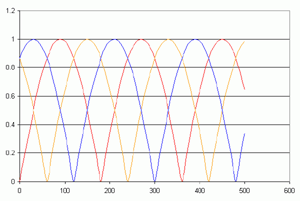
This type of 3 phase rectification is known as “6 Pulse Rectification” for obvious reasons.
The advantage of three phase rectification over single phase is the ease of achieving a reasonable level of smoothing for larger power loads without the requirement for expensive smoothing components. At low power the single phase systems often have the advantage of cost.
Other methods of 3 phase rectification involve the use of separate Star and Delta outputs to produce “12 Pulse Rectification”, each secondary is rectified with its own 3 phase bridge and the rectifier outputs may be connected either in parallel or in series. This will reduce the ripple down to 2.5%, this system also reduces the effects of current harmonics on the supply. Generally for low power applications this will not be required.
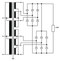
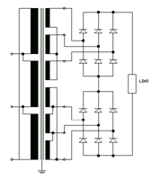
12 Pulse Parallel Connected - 12 Pulse Series Connected
If required we can also design for larger number pulse systems (18 and 24) using interconnected star configurations.
Variable D.C. supplies
Some applications require the D.C. voltage to be variable e.g. the speed control for a D.C. motor. This can be achieved by the addition of a variable transformer to the circuits described above. The variable transformer will adjust the A.C. input to the transformer and the D.C. output voltage will follow the A.C. variation.
Regulated DC supplies
Do not confuse regulated D.C. supplies with Smoothed D.C. supplies.
A smoothed D.C. supply will offer a D.C. voltage level with a ripple voltage where the average D.C. voltage level will rise and fall with the normal fluctuations in the A.C. supply voltage.
A regulated D.C. voltage will offer a stable D.C. output voltage with extremely low ripple that does not vary as the input supply fluctuates. Regulated D.C. supplies require much more complex circuits than those described above.
Rectifier Design
Diode devices are rated for a specific current at 25°C, however during operation they generate heat increasing their temperature. As the temperature of the device increases the maximum diode current has to be de-rated. Heat-sink components are usually required to limit the temperature the diodes can reach in operation by dissipating most of heat they generate.
Carroll & Meynell adopt a conservative policy when designing our own rectifier units for D.C. load currents rated up to 30A to ensure the reliability of the units.
Above this rating we use rectifier units built to order by a reputable manufacturer with specialist expertise in this area.
